Waveguide Horn Antennas - Sectoral Horn Antenna |
|---|
Sectoral Waveguide Horn Antennas
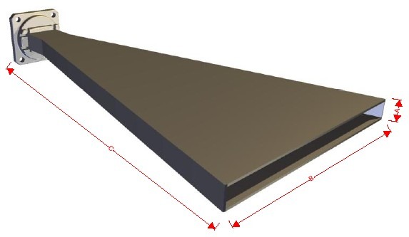
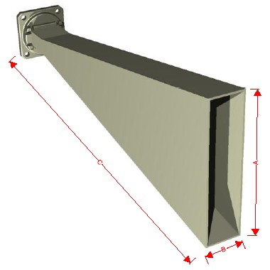
Narda-MITEQ manufactures a wide array of microwave sectoral horn antenna in both E and H plane configurations for rectangular waveguide.
In certain instances the use of the sectoral horn antenna is an effective method of achieving broadband ’broadcast’ type coverage required in base station transmission systems. Other uses include narrow field identification required in traffic control systems.
Both E plane sectoral horn antenna and H plane sectoral horn antenna configurations are usable for either vertical or horizontally polarized applications and provide the maximum beam width in the un-flared dimension.
Units we offer are true sectoral horn antenna parallel side designs. Only one waveguide dimension is flared with the other sides of the sectoral horn antenna remaining parallel. This makes for the large fan type coverage in the un-flared plane and a considerably narrower beam in the other plane.
Please call us with your specifications to discuss your sectoral horn antenna requirements with one of our RF design engineers.
Waveguide Horn Antenna:
High Gain Horn Antenna
Standard Gain Horn Antenna
Wide Band Horn Antenna
Coaxial Input Horn Antenna:
High Gain Coaxial Input Horn Antenna
Standard Gain Coaxial Input Horn Antenna
| Sectoral Horn Antenna | |
|---|---|
|
Standard Features: Optional Features: |
|
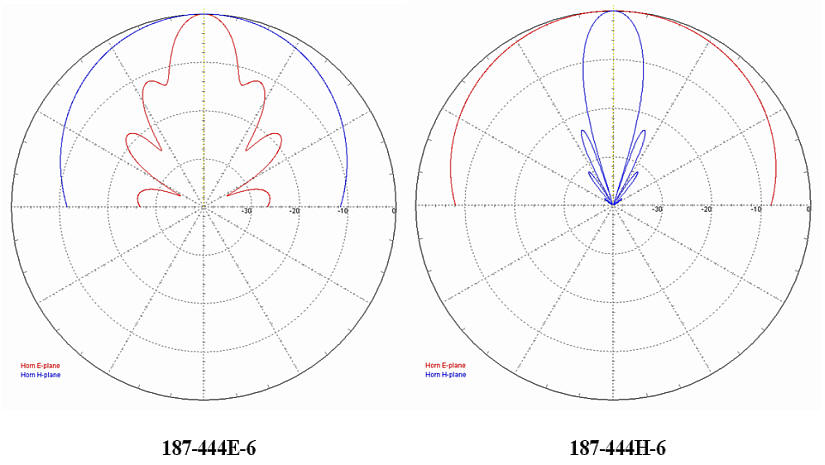 The above data plots represent typical gain data for WR187 sectoral horn antennas. Gain shown is a computer simulation taken at the mid band frequency, 5.0 GHz |
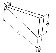
| E Plane Sectoral Horn Antenna | ||||||||||
|---|---|---|---|---|---|---|---|---|---|---|
| WG Size | Frequency (GHz) |
Model No.* |
Gain (dB) |
3dB Beam |
Typical Data |
Outline | ||||
| E Plane |
H Plane |
Size (In)** | ||||||||
| A | B | C** | ||||||||
| WR430 | 1.70 - 2.60 | 430-444E-2 | 14.5 | 15.50 | 77.20 | 19.29 | 4.30 | 28.00 | ||
| WR284 | 2.60 - 3.95 | 284-444E-6 | 14.5 | 15.50 | 76.80 | 12.42 | 2.84 | 21.70 | ||
| WR187 | 3.95 - 5.85 | 187-444E-6 | 14.5 | 15.50 | 76.40 | 7.88 | 1.87 | 19.00 | ||
| WR159 | 4.90 - 7.05 | 159-444E-2 | 14.5 | 15.50 | 76.80 | 6.77 | 1.59 | 15.40 | ||
| WR137 | 5.85 - 8.20 | 137-444E-2 | 14.5 | 15.10 | 75.00 | 5.79 | 1.37 | 15.20 | ||
| WR112 | 7.05 - 10.0 | 112-444E-6 | 14.5 | 16.00 | 78.90 | 4.77 | 1.12 | 12.08 | ||
| WR90 | 8.20 - 12.4 | 90-444E-6 | 14.5 | 15.50 | 77.00 | 3.82 | 0.90 | 10.67 | ||
| WR75 | 10.0 - 15.0 | 75-444E-6 | 14.5 | 15.40 | 76.40 | 3.19 | 0.75 | 8.10 | ||
| WR62 | 12.4 - 18.0 | 62-444E-6 | 14.5 | 15.50 | 76.60 | 2.38 | 0.62 | 6.71 | ||
| WR51 | 15.0 - 22.0 | 51-444E-6 | 14.5 | 15.50 | 76.70 | 2.19 | 0.51 | 5.12 | ||
| WR42 | 18.0 - 26.5 | 42-444E-6 | 14.5 | 15.50 | 76.80 | 1.80 | 0.42 | 4.46 | ||
| WR28 | 26.5 - 40.0 | 28-444E-6 | 14.5 | 15.50 | 76.80 | 1.18 | 0.28 | 3.38 | ||
|
* The Standard Model Numbers above are the most common parts ordered for size, material and flange. However, these models can easily be altered to accommodate your needs by using the Model # code system to the left. Above models are not supplied with calibration data. Select /CAL option to receive actual Gain vs. Frequency taken in the far field. Click this link for a sample of data: "Calibration Data Sample" ** Overall length can vary depending on flange type. *** Gain and 3dB Beam width values have been calculated by computer simulation. **** More than one option per Horn is possible. For example: 90-444E-6/CAL/RD/BR would contain all of the described options |
||||||||||||||||||||||||||||||
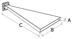
| H Plane Sectoral Horn Antenna | ||||||||||
|---|---|---|---|---|---|---|---|---|---|---|
| WG Size | Frequency (GHz) |
Model No.* |
Gain (dB) |
3dB Beam Width*** |
Typical Data |
Outline | ||||
| Size (In)** | ||||||||||
| E Plane |
H Plane |
A | B | C** | ||||||
| WR430 | 1.70 - 2.60 | 430-444H-2 | 11.5 | 99.40 | 16.50 | 2.150 | 28.74 | 34.50 | ||
| WR284 | 2.60 - 3.95 | 284-444H-6 | 11.5 | 101.80 | 15.60 | 1.340 | 19.29 | 25.00 | ||
| WR187 | 3.95 - 5.85 | 187-444H-6 | 11.5 | 102.20 | 15.50 | 0.872 | 11.81 | 18.45 | ||
| WR159 | 4.90 - 7.05 | 159-444H-2 | 11.5 | 99.10 | 16.00 | 0.795 | 9.84 | 15.06 | ||
| WR137 | 5.85 - 8.20 | 137-444H-2 | 11.5 | 103.70 | 13.60 | 0.622 | 8.66 | 14.04 | ||
| WR112 | 7.05 - 10.0 | 112-444H-6 | 11.5 | 104.70 | 15.30 | 0.497 | 7.09 | 12.09 | ||
| WR90 | 8.20 - 12.4 | 90-444H-6 | 11.5 | 104.70 | 15.40 | 0.400 | 5.51 | 10.40 | Data | |
| WR75 | 10.0 - 15.0 | 75-444H-6 | 11.5 | 99.10 | 15.30 | 0.375 | 5.70 | 8.67 | Data | |
| WR62 | 12.4 - 18.0 | 62-444H-6 | 11.5 | 98.90 | 15.50 | 0.311 | 4.21 | 6.87 | ||
| WR51 | 15.0 - 22.0 | 51-444H-6 | 11.5 | 99.10 | 15.50 | 0.255 | 3.46 | 7.44 | ||
| WR42 | 18.0 - 26.5 | 42-444H-6 | 11.5 | 108.50 | 15.00 | 0.170 | 2.76 | 5.94 | ||
| WR28 | 26.5 - 40.0 | 28-444H-6 | 11.5 | 99.00 | 16.80 | 0.140 | 1.75 | 5.50 | ||
|
* The Standard Model Numbers above are the most common parts ordered for size, material and flange. However, these models can easily be altered to accommodate your needs by using the Model # code system to the left. Above models are not supplied with calibration data. Select /CAL option to receive actual Gain vs. Frequency taken in the far field. Click this link for a sample of data: "Calibration Data Sample" ** Overall length can vary depending on flange type. *** Gain and 3dB Beam width values have been calculated by computer simulation. **** More than one option per Horn is possible. For example: |
||||||||||||||||||||||||||||||
