| GENERAL SPECIFICATIONS ( All Options ) BROADWALL DIRECTIONAL COUPLERS |
|
|---|---|
|
Electrical |
Mechanical |
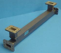
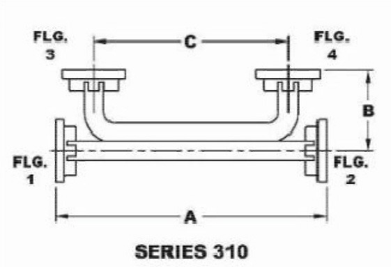
| 4 Waveguide Port - Broadwall Directional Coupler | ||||||
|---|---|---|---|---|---|---|
 |
 |
|||||
| WG Size | Freq. (GHz) | Standard Model No.* |
Dim. A inches** |
Dim. B inches |
Dim. C inches** |
Outline Drawings |
| WR650 | 1.12 - 1.70 | 650-310A-dB-2-2-2-2 | 37.0 | 8.00 | 29.0 | |
| WR430 | 1.70 - 2.60 | 430-310A-dB-2-2-2-2 | 35.0 | 5.50 | 30.0 | |
| WR284 | 2.60 - 3.95 | 284-310A-dB-6-6-6-6 | 31.0 | 6.00 | 24.0 | |
| WR229 | 3.30 - 4.90 | 229-310A-dB-2-2-2-2 | 28.0 | 5.00 | 21.0 | |
| WR187 | 3.95 - 5.85 | 187-310A-dB-6-6-6-6 | 25.0 | 4.00 | 19.0 | |
| WR159 | 4.90 - 7.05 | 159-310A-dB-2-2-2-2 | 23.0 | 3.00 | 17.5 | |
| WR137 | 5.85 - 8.20 | 137-310A-dB-2-2-2-2 | 20.0 | 3.00 | 15.5 | |
| WR112 | 7.05 - 10.0 | 112-310A-dB-6-6-6-6 | 18.0 | 2.50 | 14.0 | |
| WR90 | 8.20 - 12.4 | 90-310A-dB-6-6-6-6 | 17.0 | 2.00 | 13.5 | Dwg |
| WR75 | 10.0 - 15.0 | 75-310A-dB-6-6-6-6 | 15.0 | 1.50 | 12.0 | |
| WR62 | 12.4 - 18.0 | 62-310A-dB-6-6-6-6 | 13.0 | 1.25 | 10.5 | Dwg |
| WR51 | 15.0 - 22.0 | 51-310A-dB-6-6-6-6 | 12.0 | 1.25 | 9.50 | |
| WR42 | 18.0 - 26.5 | 42-310A-dB-6-6-6-6 | 11.0 | 1.25 | 8.50 | |
| WR34 | 22.0 - 33.0 | 34-310A-dB-6-6-6-6 | 9.00 | 1.25 | 7.50 | |
| WR28 | 26.5 - 40.0 | 28-310A-dB-6-6-6-6 | 10.0 | 1.00 | 8.00 | |
|
* The Standard Model Numbers above are the most common parts ordered for size, material and flange. However, these models can easily be altered for your needs by using the Model # code system to the left. ** The dimensions shown are for units with coupling values of 20dB or higher; for lower coupling values (3, 6, 10 dB) the "A" and "C" dimensions could be larger, contact factory for size. Option: Add /PT to part number for pressure sealed unit to 15 psi. |
||||||||||||||||||||||||||||||||||||||||||||||||||||||||||||||||||||||||||||||||||||||||||
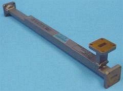
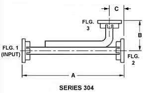
| 3 Waveguide Port - Broadwall Directional Coupler | ||||||
|---|---|---|---|---|---|---|
 |
 |
|||||
| WG Size | Freq. (GHz) | Standard Model No.* |
Dim. A inches |
Dim. B inches |
Dim. C inches |
Outline Drawings |
| WR284 | 2.60 - 3.95 | 284-304A-dB-6-6-6 | 50.25 | 6.00 | 2.66 | Dwg |
| WR229 | 3.30 - 4.90 | 229-304B-dB-2-2-2 | 42.00 | 6.81 | 1.84 | Dwg |
| WR187 | 3.95 - 5.85 | 187-304A-dB-6-6-6 | 34.62 | 6.44 | 1.81 | Dwg |
| WR159 | 4.90 - 7.05 | 159-304B-dB-2-2-2 | 32.50 | 4.50 | 1.56 | Dwg |
| WR137 | 5.85 - 8.20 | 137-304B-dB-2-2-2 | 26.50 | 3.06 | 1.56 | Dwg |
| WR112 | 7.05 - 10.0 | 112-304B-dB-6-6-6 | 18.62 | 3.06 | 1.56 | Dwg |
| WR90 | 8.20 - 12.4 | 90-304A-dB-6-6-6 | 16.68 | 2.50 | 1.50 | Dwg |
| WR75 | 10.0 - 15.0 | 75-304B-dB-6-6-6 | 15.00 | 2.50 | 1.25 | Dwg |
| WR62 | 12.4 - 18.0 | 62-304B-dB-6-6-6 | 13.75 | 2.18 | 0.66 | Dwg |
| WR51 | 15.0 - 22.0 | 51-304B-dB-6-6-6 | 11.50 | 1.25 | 0.66 | Dwg |
| WR42 | 18.0 - 26.5 | 42-304B-dB-6-6-6 | 9.50 | 1.25 | 0.75 | Dwg |
| WR34 | 22.0 - 33.0 | 34-304B-dB-6-6-6 | 9.00 | 1.25 | 0.75 | Dwg |
| WR28 | 26.5 - 40.0 | 28-304A-dB-6-6-6 | 8.00 | 1.12 | 0.75 | Dwg |
|
* The Standard Model Numbers above are the most common parts ordered for size, material and flange. However, these models can easily be altered for your needs by using the Model # code system to the left. Option: Add /PT to part number for pressure sealed unit to 15 psi. |
||||||||||||||||||||||||||||||||||||||||||||||||||||||||||||||||||||||||
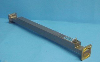
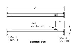
| 2 Waveguide Ports, 1 SMA Port - Broadwall Directional Coupler | |||||
|---|---|---|---|---|---|
 |
 |
||||
| WG Size | Freq. (GHz) | Standard Model No.* |
Dim. A inches |
Dim. B inches |
Dim. C inches |
| WR430 | 1.70 - 2.60 | 430-305A-dB-2-2 | 60.00 | 3.76 | 5.00 |
| WR284 | 2.60 - 3.95 | 284-305A-dB-6-6 | 50.25 | 2.55 | 2.66 |
| WR229 | 3.30 - 4.90 | 229-305B-dB-2-2 | 42.00 | 2.22 | 2.25 |
| WR187 | 3.95 - 5.85 | 187-305A-dB-6-6 | 34.62 | 1.81 | 2.00 |
| WR159 | 4.90 - 7.05 | 159-305B-dB-2-2 | 32.50 | 1.82 | 1.75 |
| WR137 | 5.85 - 8.20 | 137-305B-dB-2-2 | 26.50 | 1.56 | 1.75 |
| WR112 | 7.05 - 10.0 | 112-305B-dB-6-6 | 18.62 | 1.38 | 1.75 |
| WR90 | 8.20 - 12.4 | 90-305A-dB-6-6 | 16.68 | 1.20 | 1.75 |
| WR75 | 10.0 - 15.0 | 75-305B-dB-6-6 | 15.00 | 1.17 | 1.50 |
| WR62 | 12.4 - 18.0 | 62-305B-dB-6-6 | 13.75 | 1.05 | 1.00 |
| WR51 | 15.0 - 22.0 | 51-305B-dB-6-6 | 11.50 | 0.97 | 0.75 |
| WR42 | 18.0 - 26.5 | 42-305B-dB-6-6** | 9.50 | 0.84 | 0.75 |
| WR34 | 22.0 - 33.0 | 34-305B-dB-6-6** | 9.00 | 0.84 | 0.75 |
| WR28 | 26.5 - 40.0 | 28-305A-dB-6-6** | 8.00 | 0.79 | 0.88 |
|
* The Standard Model Numbers above are the most common parts ordered for size, material and flange. However, these models can easily be altered for your needs by using the Model # code system to the left. ** These units are supplied with 2.9mm (K-type) connectors - square flange. Option: Add /PT to part number for pressure sealed unit to 15 psi. |
||||||||||||||||||||||||||||||||||||||||||||||||||||||||
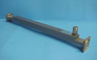
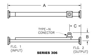
| 2 Waveguide Ports, 1 Type-N Port - Broadwall Directional Coupler | |||||
|---|---|---|---|---|---|
 |
 |
||||
| WG Size | Freq. (GHz) | Standard Model No.* |
Dim. A inches |
Dim. B inches |
Dim. C inches |
| WR430 | 1.70 - 2.60 | 430-306A-dB-2-2 | 60.00 | 4.12 | 5.00 |
| WR284 | 2.60 - 3.95 | 284-306A-dB-6-6 | 50.25 | 2.91 | 2.66 |
| WR229 | 3.30 - 4.90 | 229-306B-dB-2-2 | 42.00 | 2.58 | 2.25 |
| WR187 | 3.95 - 5.85 | 187-306A-dB-6-6 | 34.62 | 2.17 | 2.00 |
| WR159 | 4.90 - 7.05 | 159-306B-dB-2-2 | 32.50 | 2.18 | 1.75 |
| WR137 | 5.85 - 8.20 | 137-306B-dB-2-2 | 26.50 | 1.92 | 1.75 |
| WR112 | 7.05 - 10.0 | 112-306B-dB-6-6 | 18.62 | 1.73 | 1.75 |
| WR90 | 8.20 - 12.4 | 90-306A-dB-6-6 | 16.68 | 1.56 | 1.75 |
| WR75 | 10.0 - 15.0 | 75-306B-dB-6-6 | 15.00 | 1.52 | 1.50 |
| WR62 | 12.4 - 18.0 | 62-306B-dB-6-6 | 13.75 | 1.41 | 1.00 |
|
* The Standard Model Numbers above are the most common parts ordered for size, material and flange. However, these models can easily be altered for your needs by using the Model # code system to the left. Option: Add /PT to part number for pressure sealed unit to 15 psi. |
||||||||||||||||||||||||||||||||||||||||||||||||||||||||