Waveguide To Coax Right Angle High Power Adapter |
|---|
High Power Waveguide To Coaxial Adapters
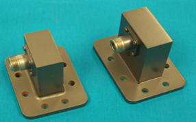
Narda-MITEQ manufactures Very High Power, Right Angle Waveguide to Coax Adapters covering the full frequency range for Rectangular Waveguide with multiple flange options.
These high power right angle adapters are configured with custom airline type N female connectors with a grounded center connector for optimum thermal transfer and CW power handling.
We also manufacture a complete line of standard power Waveguide To Coaxial Right Angle Adapters here.
These adapters can be custom designed to add heat sinks when higher power is required. For more information feel free to call us and discuss your needs with one of our design engineers.
| Ultra High Power Waveguide To Coaxial Right Angle Adapters | |
|---|---|
 |
GENERAL SPECIFICATIONS - Electrical
|

|
|
| Ultra High Power Type-N Female Waveguide To Coaxial Right Angle Adapters |
|||||||
|---|---|---|---|---|---|---|---|
| WG Size | Freq (GHz) | High Power Model No.* |
Peak Power (kW) |
Power CW (Watts) |
Theoretical I.L. (Max)** |
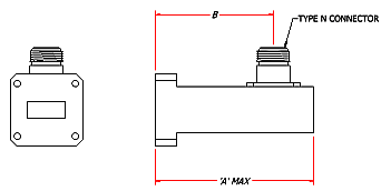
Dimension "A" Max |
Dimension "B" |
| WR284 | 2.60 - 3.95 | 284-253UHPA-6 | 6 | 2000 | 0.08 | 7.75 | 6.25 |
| WR229 | 3.30 - 4.90 | 229-253UHPA-2 | 6 | 1800 | 0.09 | 6.15 | 5.00 |
| WR187 | 3.95 - 5.85 | 187-253UHPA-6 | 6 | 1500 | 0.09 | 5.25 | 4.25 |
| WR159 | 4.90 - 7.05 | 159-253UHPA-2 | 6 | 1500 | 0.10 | 4.30 | 3.50 |
| WR137 | 5.85 - 8.20 | 137-253UHPA-2 | 6 | 1350 | 0.10 | 3.60 | 2.90 |
| WR112 | 7.05 - 10.0 | 112-253UHPA-6 | 6 | 1100 | 0.11 | 3.20 | 2.50 |
| WR102 | 7.00 - 11.0 | 102-253UHPA-6 | 6 | 1000 | 0.13 | 3.20 | 2.50 |
| WR90 | 8.20 - 12.4 | 90-253UHPA-6 | 6 | 1000 | 0.15 | 2.80 | 2.20 |
| WR75 | 10.0 - 15.0 | 75-253UHPA-6 | 6 | 900 | 0.15 | 2.30 | 1.75 |
| WR62 | 12.4 - 18.0 | 62-253UHPA-6 | 6 | 850 | 0.16 | 2.00 | 1.50 |
|
* The Standard Model Numbers above are the most common parts ordered for size, material and flange. However, these models can easily be altered for your needs by using the Model # code system at left. ** Insertion Loss for WG to coax adapter is difficult to measure due to the very low loss and setup. The max I.L. figure quoted is based on the theoretical losses due to connector, waveguide and reflection all taken at the highest Freq. and max value. |
||||||||||||||||||||||||||||||